
How to make 12v and 10amp power supply easy with circuit diagram YouTube
Generally speaking, a 12V DC power supply circuit diagram will include a power source (a battery, solar panel, or AC adapter), a switch, a resistor, a capacitor, and a voltage regulator. The switch will allow you to turn the power supply on and off, the resistor and capacitor will prevent any sudden changes in voltage, and the voltage regulator.
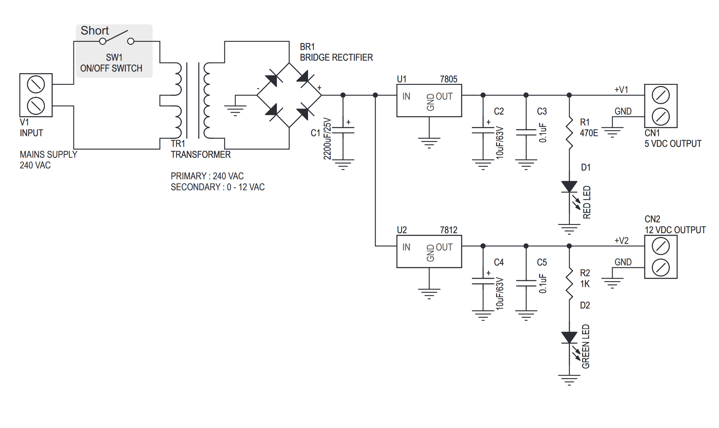
5V & 12V Regulated Power Supply
The most commonly used type of power supply circuit is the SMPS (Switching Mode Power Supply), you can easily find this type of circuits in your 12V adapter or Mobile/Laptop charger. In this tutorial, we will learn how to build a 12v SMPS circuit that would convert AC mains power to 12V DC with a maximum current rating of 1.25A. This circuit.

How to make adjustable current 12v power supply with circuit diagram YouTube
A linear 12V power supply is easy to build, as it involves a transformer, diode bridge circuit, a 12V DC regulator and bypass capacitors to minimize fluctuation of the voltage. The choice of the DC regulator determines the output load that can be handled by the power supply .
12V DC Power Supply without Transformer Power Supply Circuits
Here this circuit diagram is for +12V regulated (fixed voltage) DC power supply. This power supply circuit diagram is ideal for an average current requirement of 1Amp. This circuit is based on IC LM7812. It is a 3-terminal (+ve) voltage regulator IC. It has short circuit protection , thermal overload protection. LM7812 IC is from LM78XX series.
12V 3A Power Supply Circuit Using 2N3055 Transistor
The most commonly used of type of power supply circuit is the SMPS (Switching Mode Power Supply), you can easily find this type of circuits in your 12V adapter or Mobile/Laptop charger. In this tutorial we will learn how to build a 12v SMPS circuit that would convert AC mains power to 12V DC with a maximum current rating of 1.25A.
12v Power Supply Circuit Diagram
It provides the necessary electrical energy required to power various devices or components. In this article, we will discuss a 12V variable power supply circuit diagram using 2N3055, BC547, and BC557 transistors. These transistors, along with a 15V zener diode, play a crucial role in regulating the output voltage and current of the power supply.
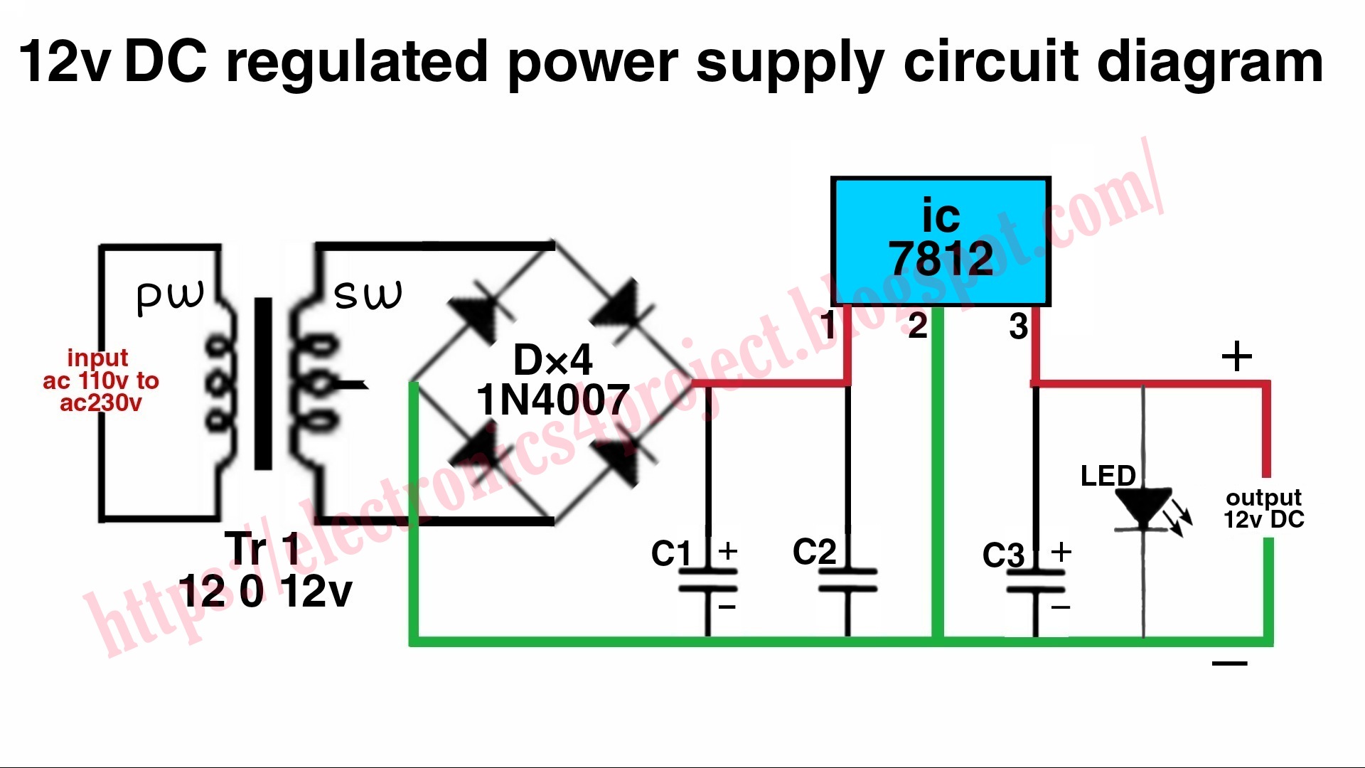
12 Volt Dc Regulated Power Supply Circuit Diagram
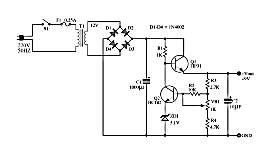
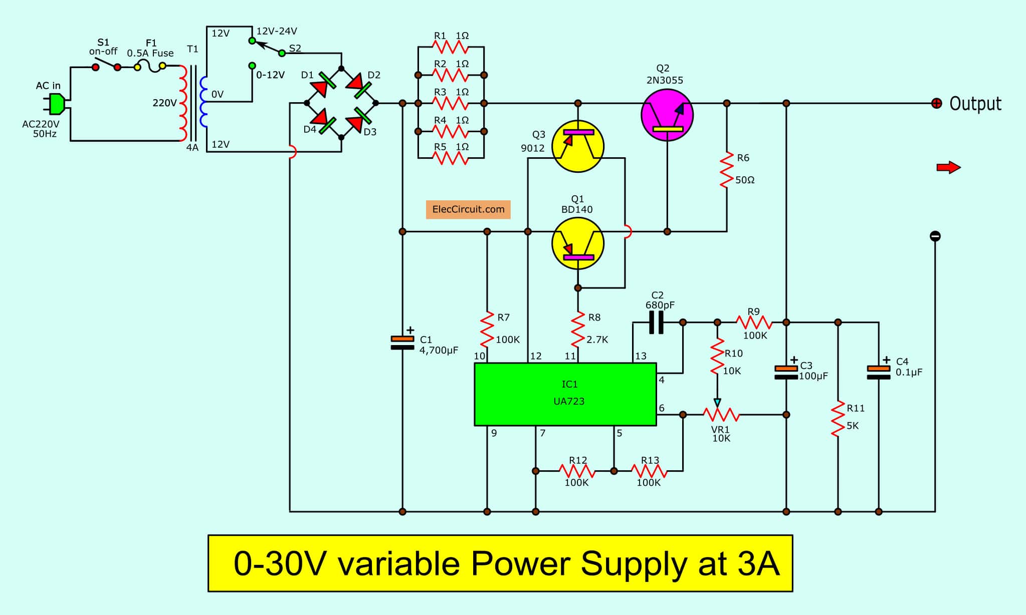
The regulated power supplies are also known as linear power supplies. A simple regulated power supply circuit mainly consists of an ordinary power supply with a device that regulates the output voltage according to the requirement. Here we will build a circuit with an output voltage range of up to 12V and current output of up to 3A which can be.
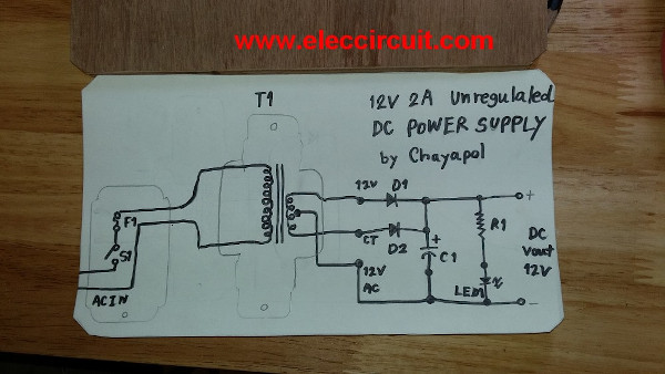
Simple 12V 2A Power supply circuit
Compared to the original 12VHPWR connector, the new 12V-2x6 connector has slightly (0.1mm) shorter sensing pins while the conductor terminals are 0.15mm longer. This might not sounds like a huge difference, but it matters in ensuring that the power cable has been properly connected to whatever device is going to be pulling power from your.
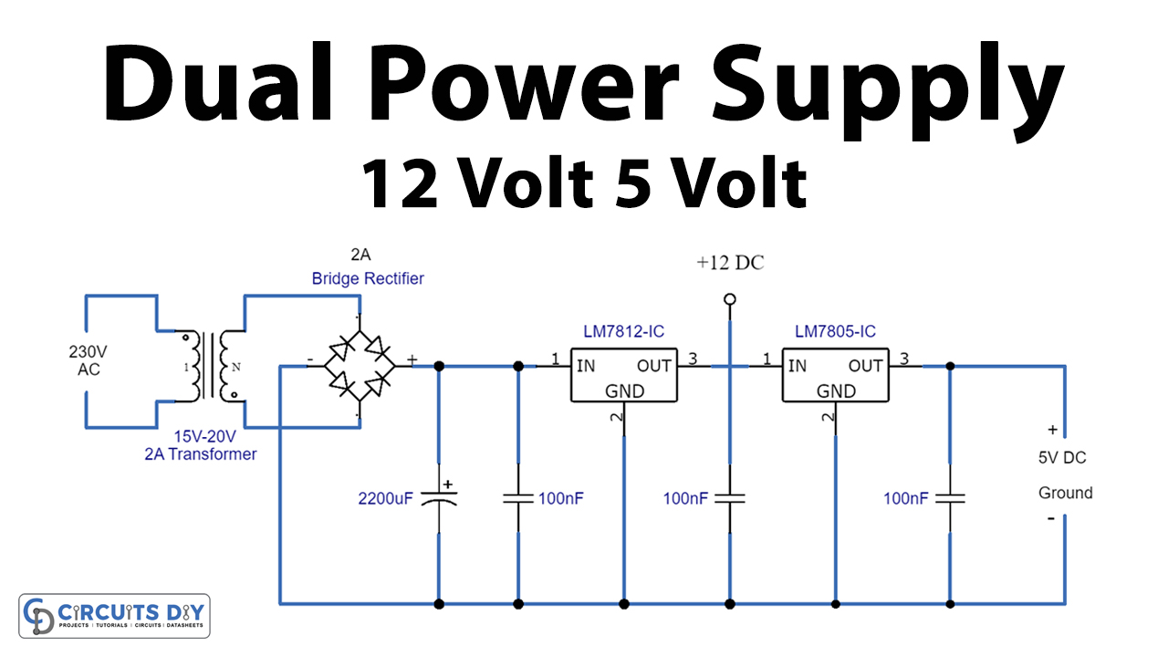
12v And 5v Dual Power Supply Circuit Wiring Diagram and Schematics
12V 1A Power Supply Circuit Design using VIPer22A. Switched mode power supply circuits (SMPS) are most often in required in many electronic designs to convert the AC mains voltage to suitable level of DC voltage for the device to operate. This type of AC-DC converters takes in the 230V/110V AC mains voltage as input and converts it to low level.
dual voltage power supply 12 volt under Repositorycircuits 31752 Next.gr
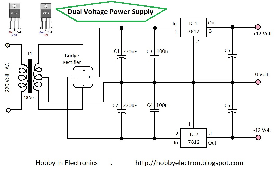
Dual Power regulator +12V/-12V using 7812, 7912. 24V 2A supply circuit Diagram. 18V DC voltage regulator using 7818. 5V Low Dropout Regulator Circuit using transistor and LED Make 5V low dropout regulator circuit using transistor and LED lowest voltage input is 6V so across it is 1V only, make output is 5V 0.5A.
12v Switching Power Supply Circuit Diagram
Featuring Over-Voltage, Over-Current, Short-Circuit, and Over-Temperature (190°F) Protections ; Stable Performance with an MTBF of Over 100,000 Hours at 25°C and 80% Load ;. HiLetgo 5pcs 3.3V 5V Power Supply Module for MB102 102 Prototype Breadboard DC 6.5-12V or USB Power Supply Module.

12 Volt DC Power Supply Circuit
6 Working Explanation. 7 Applications. In this tutorial, we are going to design a " Dual Mode Power Supply +12volt and -12volt". The +12V and +12V Dual Power Supply Circuit work by converting AC into both +12 volts and -12 volts DC. This is the reason for its name "dual power supply".
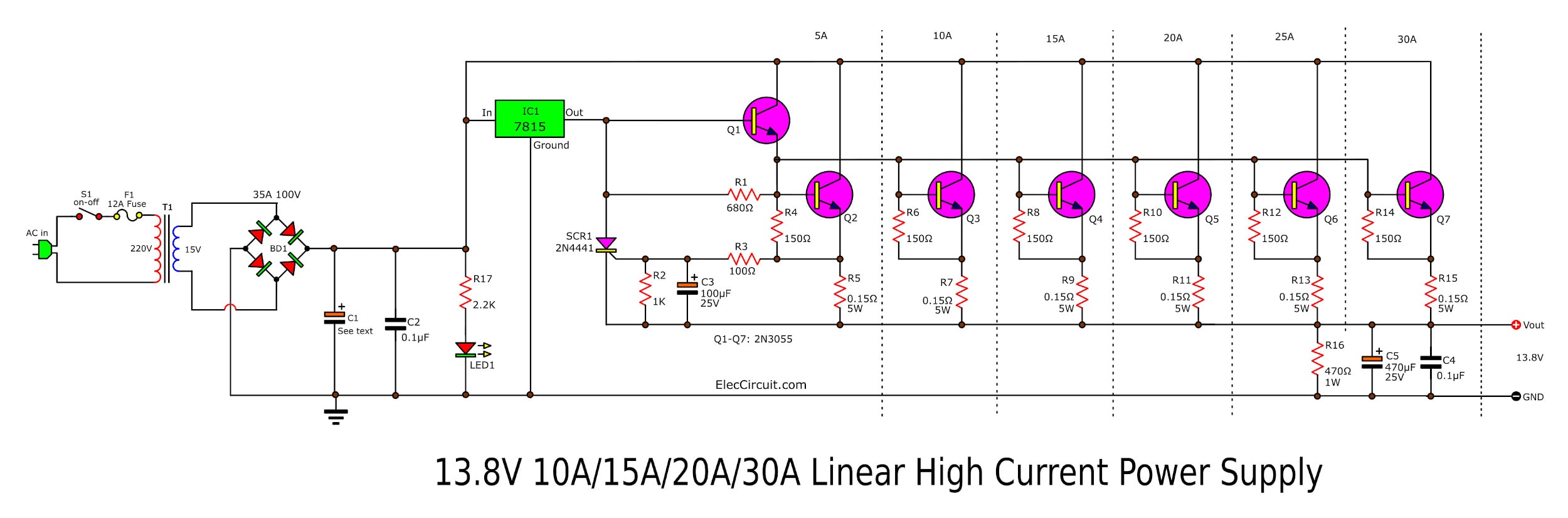
High Current 12V13.8V at 30A,25A,20A,15A Power Supply Elec Circuit
The essential components of a 12v regulated power supply include a transformer, rectifier, filter, voltage regulator, and overload protection. The transformer takes in alternating current (AC) from a wall socket and connects to the rectifier, which changes the AC into direct current (DC). The DC is then filtered to remove any noise before being.

12 Volt 10 Ampere DC Power Supply Circuit
The objective of this project is to convert 220V AC supply in to +12V and -12v DC supply, that is why it is named Dual Power Supply as we get positive and negative 12v power supply at the same time. This can be achieved in simple three steps: Firstly, 220V AC is converted into 12V AC by using simple step-down (220V/12V) transformer. Secondly.

How to make 12v power supply easy at home step by step with circuit diagram YouTube
12V BD139 power supply circuit. LM7812 power supply schematic. A very simple PS circuit with the basic 3 Amper version of LM7812 IC. LM317 variable power supply circuit. 2N3055 adjustable power supply schematic. This power supply circuit has a over-current protection and a good stabilized voltage. It can deliver up to 1.6 A.

12V / 20A Regulated DC Power Supply Power Supply Circuits
To build the 12V and 5V dual power supply circuit, you will need the following components: a step-down transformer (15V, 1A), regulator IC L7812, regulator IC L7805, diode 1N4004 (4 pieces), LED (1 piece), capacitors 1000uF (2 pieces), and resistor 4.7KΩ (1 piece). Start by connecting the primary side of the step-down transformer to a 230V AC.